OBD 2: Understanding EGR Monitor
2017 Smog Update Class
Understanding EGR Monitor:
Some of the Images are from your Smog License Update Class manual by AGT Training
I know coming from work and setting in a class lecture can be hard but I appreciate your effort.
This is the lecture from class repeated just encase you came in late or dose off LOL.
Understanding EGR Monitor
Understanding EGR Monitor:
A
balance air/fuel mixture is great for gas mileage in school we say it's
14.7:1, which is 14 pounds of air to one pound of fuel. If you are
performing an emissions test, this is ideal for low HC "Hydrocarbons"
and CO "Carbon Monoxide".
But if we are talking about Nox "Nitrogen Oxide" a lean air/fuel mixture isn't ideal. If the air/fuel stay this lean Nox will increase, to control Nox with the air/fuel mixture the air/fuel mixture would have to move slightly on the rich side.
Understanding EGR Monitor - How Nox is Created
At 2500 degree Fahrenheit in the combustion chamber 02 combines with N2 "Nitrogen" it will form together to become Nox but a properly working EGR valve will help in reducing Nox by reducing the combustion chamber temperature below 2500 degrees Fahrenheit.
The EGR "Exhaust Gas Re circulation" valve helps by directing inert gas into the combustion chamber. "less than 14%" Inert gas is burnt gasses in the exhaust that are directed to the combustion chamber and use to lower the combustion chamber temperature.
The inert gas will take up space within the combustion chamber and prevent oxygen from entering, less oxygen less heat, low Nox
Understanding EGR Monitor
As long as the EGR valve is functional, the intake and exhaust manifold ports are cleared the EGR circuit will help reduce Nox. If anyone of these conditions are not met, Nox will increase.
The job of the EGR monitor is to confirm or make sure the EGR circuit is working, what most mechanics get wrong is that they only check the EGR if they check it at all, hell most mechanics probably will just replace the EGR valve, hoping to fix a Nox failure without checking the whole circuit.
EGR monitors are testing the whole circuit and confirming that it's working.
Understanding EGR Monitor: Early Monitors
IMAGINE BY AGT SMOG UPDATE TRAINING MANUAL
EARLY MONITOR
Understanding EGR Monitor:
OBD2 had to be on all cars in 1996; OBD 2 is a self-emissions test, and one of the emission components is the EGR, and the EGR monitor will do just that. It monitors are should I say it will test the circuit for proper operation.
Now there where monitors before 1996, some vehicles had a potentiometer this is a variable resistor that sits on the EGR diaphragm.
When the EGR valve diaphragm moves up the pintle that is sitting on the diaphragm sends a signal back to the PCM indicating the movement and position of the EGR Diaphragm.
This signal is an indication to the computer that the valve moves and how much but it didn't tell you if the intake or exhaust ports were cleared or not clogged.
Understanding EGR Monitor: Temperature Sensor
Some
other manufacturers use a temperature sensor to confirm the operation
of the EGR. When the EGR valve opens the hot exhaust gasses flow pass
the EGR Temperature sensor, and the voltage change proves that the valve
is operational.
This operation confirms the EGR valve is operational, and the intake and the exhaust ports are not plugged.
This
was on the OBD 1 emissions control now on OBD 2 they use more precise
controls to confirm the operation of the EGR circuit.
Understanding EGR Monitor: USING MANIFOLD VACUUM TO CHECK EGR OPERATION
HOW DOES THE EGR MONITOR USE MANIFOLD VACCUM TO CHECK EGR OPERATION:
On OBD 2 vehicles when the EGR monitor runs to test the circuit, it will be using other components or systems to confirm the EGR circuit is working.
One example is using manifold vacuum remember when the EGR valve comes on let's say at idle it's causing a vacuum leak which means vacuum should drop, and pressure should increase.
(remember the EGR doesn't work at idle, this is just an explanation)
So keep this in mind for the next example; understanding this concept makes it easier in understanding how the monitor is using a vacuum to check the EGR circuit.
When a particular criterion is met, the EGR will turn on the EGR usually when the customer can not feel the vehicle is being tested.
When the EGR is open, the pressure will increase, or when the EGR valve is close, the vacuum will Increase.
Here is another way of saying this; if the PCM sees low vacuum "increase pressure" it means there is EGR Flow. Also high vacuum "decrease pressure" means Low EGR Flow.
How is the PCM "Power Train Control Module" seeing this vacuum change will it has to be on the MAP "Manifold Absolute Pressure" sensor? The MAP sensor works off manifold pressure so the PCM can see any change in the intake manifold.
So let's think about this when the correct conditions have met the monitor will test the EGR Valve. An example would be on deceleration the PCM will open the EGR in this situation the vacuum is high pressure is low.
But when the EGR is open on deceleration the vacuum should be high and the pressure low, when the PCM opens the EGR when the monitor is testing the circuit it's looking for an increase in manifold pressure.
If the PCM doesn't see the correct change the PCM will interpret the EGR has a nonfunctional circuit.
Understanding EGR Monitor: Differential Pressure Feedback Sensor (DPEF)
Ford's Differential Pressure Feedback Sensor (DPFE)
Some Ford's use a Differential Pressure Feedback Sensor which is similar to a MAP sensor but this sensor is located on the exhaust.
The voltage from the sensor will vary in proportionally to the pressure or vacuum in the system similar to a MAP sensor on the intake manifold. But here is the difference the DPFE EGR Sensor measures the pressure difference between two different locations in the EGR system.
One of the EGR tubes which has a fix restriction that causes a pressure drop as gasses flows through it. The faster the flow through the EGR tube the more drop across the restriction.
On this system, there are two sample hoses, one on each side of the restriction. The sensor measures the difference between these two hoses, by during this the DPFE sensor can determine the exhaust gas flow.
Understanding EGR Monitor:
When the pressure difference between there two sample hoses increases, the sensor output voltage increases to the PCM.
When the pressure is the same, the sensor output is low indicating no flow, low voltage signal to the PCM.
By monitoring this signal voltage allows the PCM to verify that the EGR is flowing when command on.
Increase voltage = Exhaust Gas Recirculation
Low voltage = No Exhaust Gas Recirculation
Understanding EGR Monitor: Using O2 Sensor To check the EGR
O2 SENSOR REACTION OR STFT SHIFT
Some manufacturers will watch the O2 voltage or STFT "Short Term Fuel Trim" to monitor EGR operation.
When the correct conditions are met and the EGR close, during testing the PCM opens the EGR and watches the shift in the O2 sensor voltage.
Remember the EGR displaces O2 so the voltage should rise, if the O2 sensor voltage goes lean the circuit isn't functional.
If the EGR didn't open the monitor will fail the circuit and turn on the check engine light if the problem persists.
Understanding EGR Monitor: (TECH TIP)
TOO MUCH EGR (TECH TIP)
Think about this a check engine light on for excessive EGR Flow so you would imagine the valve is coming on too much.
I had this vehicle in the shop, for excessive EGR flow so I place a vacuum gauge on the vacuum line to the EGR valve and drove the car no vacuum. Next, I check the signal from the PCM to the EGR solenoid while driving no signal to the solenoid to operate the EGR.
In other words, the valve wasn't functional, think about this the code was for excessive EGR flow but during my diagnosis, the EGR wasn't working, and there was no signal to the valve to make it work.
But how did the PCM EGR monitor fail the circuit for excessive EGR Flow?
So I check the signal wire that goes to the PCM, the voltage reading was 4.0 volts all of the time this is why there was an excessive flow code, the EGR position sensor was defective.
The sensor was indicating the valve was fully open in all ranges.
Now the reason we had no signal to the EGR Solenoid was that the EGR sensor indicated excessive EGR, so the PCM saw no need to energize the solenoid.
Some manufacturers watch the position sensor at idle or KOEO "Key on Engine Off" so if the voltage is supposed to read .5 volts and it reads 4.0 volts a code will set for excessive EGR flow.
Understanding EGR Monitor: How to test the Circuit
IMAGINE BY AGT TRAINING
HOW TO TEST THE CIRCUIT
In
your classroom manual by AGT update training course pg. 1-103 - 104 they talk
about four different test. No Flow – Too much Flow – Position – Circuit
Fault
I'm going to try to explain some examples I have came across when testing a EGR circuit for a failed component.
Understanding EGR Monitor
EGR MONITOR
How
does the EGR monitor test the EGR system it's usually looking for to
much flow or no flow? The PCM can use the MAP sensor, EGR position
sensor, EGR Temperature sensor or Fuel trim to monitor EGR operation.
When
the check engine light comes on for the EGR it has a freeze frame
associated with the trouble code, use the freeze frame and try to
diagnose the circuit under these same conditions. The freeze frame doesn't work all of the time but it can be very useful, especially if you have a dyno.
You
can also use your scan tool "not code reader" in the Bidirectional mode
and perform a functionality test to confirm the operation of the valve.
Keep in mind you are commanding the EGR to function using your scan
tool, if the PCM receives no input, the valve or circuit will not
function under normal conditions.
Understanding EGR Monitor: Using a Scan Tool
Using
the scan tool will give you a clue in what direction to take your
diagnoses. Example if you operate the EGR at idle, and there is no
response bad EGR valve, plugged port or electrical problem.
Another test would be to run the EGR and monitor the EGR temperature sensor or the EGR position sensor voltage if either one doesn't change possible bad valve, port or an electrical problem depending on the system.
IMAGINE BY AGT TRAINING
IN YOUR AGT TRAINING MANUAL
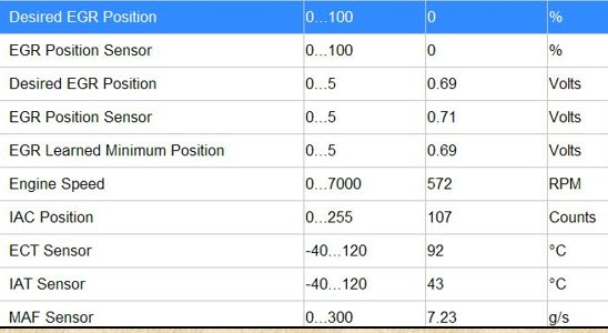
On
this slide, the EGR position is 0, and the actual position is also 0
these are good readings especially if the vehicle is at idle.
You would have a problem if the vehicle is at idle and the desired value is lower than the current value; this could be caused by an EGR valve sticking open.
I have seen on GM Astro Vans when the vehicle ran rich because of this problem
pay attention at the Learn minimum value on the scan data. If the EGR
PID value is higher than the learned value, it's partially open.
Understanding EGR Monitor: Using a Bi-Directional Control Scan Tool
EGR BI – DIRECTIONAL CONTROL
Let's face it a code Reader
or cheap scan tool can not help you much when it comes down to
troubleshooting; a good scan tool should have bi-directional control. If
you have a scan tool and you don't use the bidirectional control function, I would suggest you learn how.
Using the Bi-Directional control you command the EGR open or close. By watching the EGR Position PID on your scan tool, you can identify the EGR operation if the sensor or ports are functional.
You can determine if the circuit is shorted or the position sensor is good or maybe it's sticking.
A worn EGR valve may come on too quick or to much and cause a misfire due to dilution of the air/fuel mixture.
While watching the scan tool you command the EGR to open your manual is saying 20% but the EGR actually opens 50% this would indicate a weak EGR spring or defective EGR Valve, replace the part.
I'll appreciate you for taking the time to read this if you have any questions leave a comment also if you like the information click the like button or you can hit me up in class.
Nate "SMOGG DOGG" Davis
Emissions / Engine Performance Instructor
CLASS SCHEDULES
Emission Control 1:
B.A.R. Smog Check
Inspector Level 1
(Inspector "Smog" License):
Engine Fundamentals
8am - 12:15 pm
Summer Class
7/5/2022 -8/5/2022
Class # 799065
Emission Control 2:
B.A.R. Smog Check
Inspector Level 2
(Inspector "Smog" License):
Rules and Regulations
8am - 12:15 pm
Summer Classes
7/5/2022 - 8/5/2022
Class # 799067
Engine Performance 1:
8am - 12: 15 pm
Date: TBD
Class # 799069
Engine Performance 2:
B.A.R. Specified Diagnostic
and Repair Training
(Repair "Smog" License)
Time: TBD
Date: TBD
Class # 799071
Emission Control 1
(Inspector "Smog" License):
5:00pm - 8:45 pm
Date: TBD
Class # 799065
Emission Control 2:
(Inspector "Smog" License):
5:00pm - 8:45 pm
Date: TBD
Class # 799065
Exhaust Emissions (Update Class):
5:30 pm - 8:45 pm
Tuesday nights:
Dates: coming soon
Class # 796070