Secondary-Ignition-Pattern
Secondary-Ignition-Pattern:
The automotive ignition system has two circuits a low voltage primary circuit and a high voltage secondary circuit.
An oscilloscope displays voltage changes within a certain period of time, and the oscilloscope would be the best tool to display the voltage.
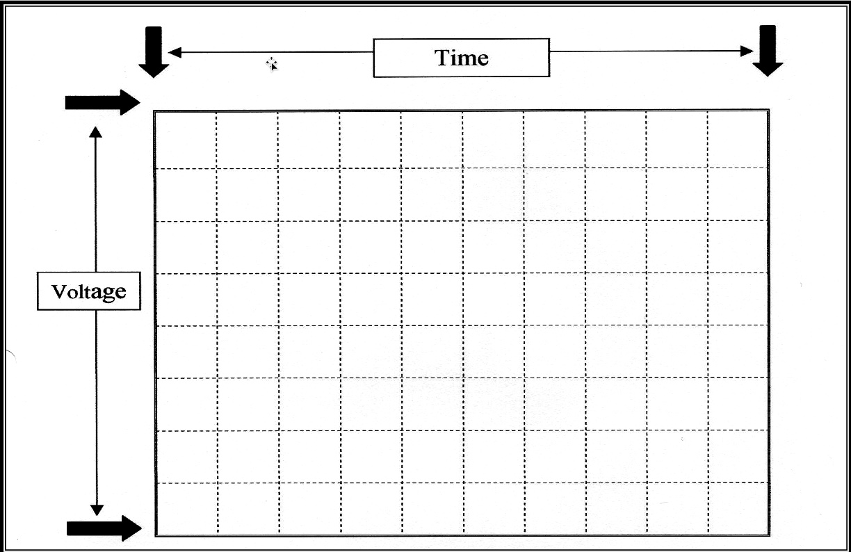
Oscilloscope works on the principle of displaying voltage over a period of time on the screen.
Voltage traces are display as a graph of voltage on a horizontal axis in a period of time.
Oscilloscope works on the principle of displaying voltage over a period of time on the screen.
Voltage traces are display as a graph of voltage vertically over a period time horizontally.
The vertical scale on the screen represents voltage and the horizontal scale indicates time.
Primary circuits are measured in volts and secondary circuits in kilovolts, or thousands of volts.
Time is measured in the percentage of one complete engine cycle or in milliseconds, thousandths of a second.
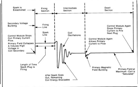
The ignition system voltage trace primary and secondary is divided into three sections
- Fire Section
- Intermediate Section
- Dwell section
When looking at the patterns you are looking for something that doesn't look normal compared to the other cylinders.
An abnormal pattern would indicate a problem in that particular cylinder.
Each pattern is best used to identify a particular malfunction.
There are usually three patterns:
Parade or Display Pattern
Raster or Stack Pattern
Superimposed pattern
A superimposed pattern voltage traces for all cylinders are displayed on top of each other.
This pattern is a quick look of the ignition system operation and can also reveal certain problems
The parade or display pattern displays voltage traces for all cylinders one after another across the screen from left to right in the firing order. This procedure allows the comparison of voltage levels between cylinders.
The parade pattern display is useful for diagnosing problems in the secondary circuit.
The raster parade pattern displays the voltage traces for all cylinders stacked one above another in the firing order. This display allows you to compare the time periods of the three sections of a voltage trace
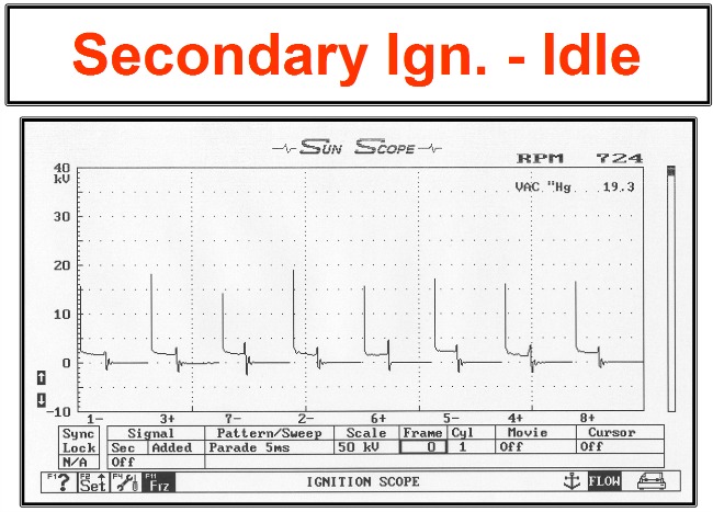
The parade or display pattern displays voltage traces for all cylinders one after another across the screen from left to right in the firing order.
This procedure allows the comparison of voltage levels between cylinders.
The parade pattern display is useful for diagnosing problems in the secondary circuit.
Secondary-Ignition-Pattern:
Distributor-less Ignition System
Secondary-Ignition-Pattern
Secondary-Ignition-Pattern
Each pair of cylinders will be fired by the same ignition coil. One cylinder will fire on the compression stroke "event" and the companion cylinder will fire at Top Dead Center on the exhaust stroke also know as "waste spark".
Resistance determines the voltage requirements for each cylinder. The cylinder on Top Dead Center Compression will have higher resistance which requires a higher voltage to ionize the spark plug gap, than its companion cylinder on TDC exhaust.
High resistance is caused by the Air Fuel Ratio "rich or lean" along with high pressures within the cylinder on Top Dead Center Compression. The cylinder on top dead center exhaust will have inert gases along with very low pressure requiring much less voltage to ionize the spark plug gap.
Secondary-Ignition-Pattern: Fouled Spark Plugs
Secondary-Ignition-Pattern
While in the parade pattern and looking for an abnormal signal you are basically comparing one signal to another.
For example, when looking for an oil-fouled plug you may see a lower than normal fire line or longer than normal spark line with no activity.
Use the different displays on the oscilloscope makes it easier to view certain sections of the ignition patterns
Example:
The display pattern makes it easier to see the fire-line when looking for a open wire or high resistance in the circuit
The raster pattern makes it easier to see the spark-line when checking for a fouled plug
There is a mini test associate with this video
Use your Tech Help Book from the zoom synchronous class as reference
Come Join my FaceBook Group: Click Here
School Web Site: Click Here
CLASS SCHEDULES
Emission Control 1:
B.A.R. Smog Check
Inspector Level 1
(Inspector "Smog" License):
Engine Fundamentals
8am - 12:15 pm
Summer Class
7/5/2022 -8/5/2022
Class # 799065
Emission Control 2:
B.A.R. Smog Check
Inspector Level 2
(Inspector "Smog" License):
Rules and Regulations
8am - 12:15 pm
Summer Classes
7/5/2022 - 8/5/2022
Class # 799067
Engine Performance 1:
8am - 12: 15 pm
Date: TBD
Class # 799069
Engine Performance 2:
B.A.R. Specified Diagnostic
and Repair Training
(Repair "Smog" License)
Time: TBD
Date: TBD
Class # 799071
Emission Control 1
(Inspector "Smog" License):
5:00pm - 8:45 pm
Date: TBD
Class # 799065
Emission Control 2:
(Inspector "Smog" License):
5:00pm - 8:45 pm
Date: TBD
Class # 799065
Exhaust Emissions (Update Class):
5:30 pm - 8:45 pm
Tuesday nights:
Dates: coming soon
Class # 796070