Primary-Ignition-System
Primary-Ignition-System:
Spark Distribution: A gear , chain or belt from the engine drives something called a distributor . Within the distributor, there was something called a set of points and a condenser.
The points are open and close with something called a cam lopes that rotated as the lips of the points rest against. When the are points close the coil saturates or charges up, when the points open the magnetic fields collapses and the coil discharges.
When the points open and close it triggers the primary ignition circuit, which in turn fires the coil.
Inside the distributor, there is something called the rotor which rotates and deliver the spark to the correct spark plug wire which ignites the spark plug.
With tighter emission standards, the ignition system needed to be improved. This when the electronic ignition system was developed to help reduce the emissions.
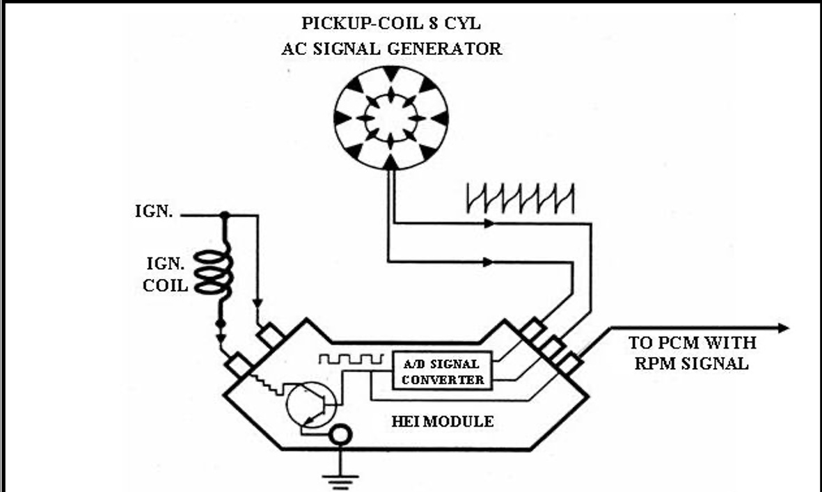
The electronic ignition system (ICM) used a
power transistor
to control the coil primary current flow.
Late-model cars stop using a distributor to direct the secondary voltage to the spark plugs. The ignition coils primary circuit control, has been replace with the Powertrain Control Module (PCM)
The PCM receives inputs from the crankshaft position sensor which in turn uses this signal to control ignition timing.
Primary-Ignition-System :
Distributor Ignition Systems
Primary-Ignition-System:
Distributor ignition systems fire the coil to ignite the spark plug during the compression stroke for each cylinder.
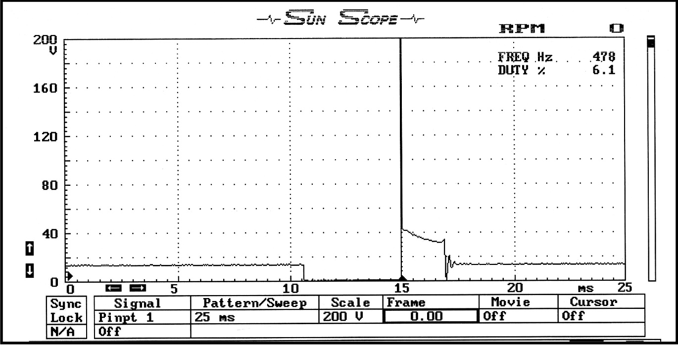
You can look at the primary ignition trigger on the negative side of the ignition coil with a test light or a Lab Scope
The conventional ignition system consists of the ignition coil, ignition distributor, spark plugs, spark wires, and a triggering device to control the primary side of the ignition coil.
The primary circuit of the ignition coil used to be a set of points on late model cars its some type of a transistor, the transistor is controlled by some other type of device as an ignition control module or powertrain module.
In point-type ignition systems, the current in the primary circuit is controlled by a mechanical switch.
The mechanical points was replace with a switching transistor that opens and closes the primary circuit of the ignition coil.
In modern ignition systems electronic ignition a Hall effect, a Variable Reluctance Sensor, or an optical sensor may be used to control the switching transistor.
Current flows from the positive terminal of the battery, through the ignition switch through a fuse to the positive terminal of the ignition coil.
The current returns to the battery through the negative terminal of the ignition coil, on through the switching device (points or a transistor) through the vehicle chassis, and to the negative terminal of the battery.
While current is flowing in the primary circuit a magnetic field builds up in the ignition coil when the points are close or the transistor is on.
With the negative side of the coil is to engage the inductance of the ignition coil becomes saturated as the current flows through the primary coil circuit. When the primary current flow is interrupted, the magnetic field collapses quickly and a high voltage is induced in the primary winding (CEMF Counter electromotive Force).
This voltage is transformed into the secondary ignition circuit through the secondary windings.
The ratio from the primary to secondary ignition is around 100:1, meaning a 300-volt primary voltage will generate approximately 30,000 volts on the secondary ignition circuit.
The voltage will only build until the firing voltage of the spark plug has been reached.
Primary-Ignition-System : Older Ignition Systems
Primary-Ignition-System
Older ignition system used ballast resistors in the circuit, this was design to add resistance to the circuit to cut back on current flow in the primary ignition circuit to the ignition coil.
However, this does not happen while the car is cranking do to the low voltage from the battery while cranking, meaning the ballast resistor is being bypassed during the cranking stage.
Because the ballast resistor is being bypassed the necessary current can reach the ignition coil for proper coil saturation.
Primary-Ignition-System : The Ignition Coils Job
Primary-Ignition-System:
The ignition coil job is to transform a low voltage to a higher voltage with low current flow. Yes, this similar to a transformer.
The reason this can happen is do to the number of turns of wire within the coil from the Primary circuit to the Secondary windings within the ignition coil.
The coils are usually designed to have a 1 : 100 turn ratio, meaning the inductive kick of voltage when the magnetic field collapses is also 1:100 ratio.
When the current flows through the ignition coil a magnetic field is created around both coil windings. When the magnetic field collapses voltage is induced in both windings.
If the primary induced voltage is 300 volts the secondary induced voltage will be 30,000 volts.
Primary-Ignition-System : Ionize Spark Plug Gap
Primary-Ignition-System:
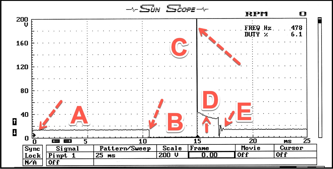
A. System voltage to the ground side of the coil, that Ignition Control Module (ICM) or Powertrain Control Module (PCM) pulls to ground for switching
B. Dwell section this is when the ICM or PCM pulls the system voltage to the ground to saturate the ignition coil.
C. When the collapse of the magnetic field for the primary coil windings collapses you will get an induced voltage spike
D. The spark line is the amount of time the spark is happening at the spark plug gap
E. The coil oscillations are the dissipating of energy from the coil after it fired, it's the ignition coil's energy from the coil windings.
The induce spike is what was required to ionize the two gaps "spark plug and rotor gap" and the remaining energy will keep spark happening,
Primary-Ignition-System : Transistors
Primary-Ignition-System
Within the ignition control module (ICM) there is a transistor that is usually a ground control switch. An NPN (Negative, Positive, Negative) transistor is an electronic switch used to control the ground side circuit for the primary ignition.
The transistor took the place of the old contact points from the distributor which open and close to control the electrical circuit.
"C' is for Collector, "E" is for Emitter and "B" is for the base which turns the transistor on and off.
A positive voltage to the base turns the transistor on and a negative voltage reading will turn off the transistor
There is also a PNP (Positive, Negative, Positive) transistor which is used to control the power side of an electrical circuit.
The Emitter and Collector still carry current, but the base works differently than the NPN transistor.
A negative voltage pulse turns it on and a positive pulse turns it off.
There is a mini test associate with this video
Use your book from the zoom synchronous class as reference
Join me in my facebook group: Click Here
School Website: Click Here
CLASS SCHEDULES
Emission Control 1:
B.A.R. Smog Check
Inspector Level 1
(Inspector "Smog" License):
Engine Fundamentals
8am - 12:15 pm
Summer Class
7/5/2022 -8/5/2022
Class # 799065
Emission Control 2:
B.A.R. Smog Check
Inspector Level 2
(Inspector "Smog" License):
Rules and Regulations
8am - 12:15 pm
Summer Classes
7/5/2022 - 8/5/2022
Class # 799067
Engine Performance 1:
8am - 12: 15 pm
Date: TBD
Class # 799069
Engine Performance 2:
B.A.R. Specified Diagnostic
and Repair Training
(Repair "Smog" License)
Time: TBD
Date: TBD
Class # 799071
Emission Control 1
(Inspector "Smog" License):
5:00pm - 8:45 pm
Date: TBD
Class # 799065
Emission Control 2:
(Inspector "Smog" License):
5:00pm - 8:45 pm
Date: TBD
Class # 799065
Exhaust Emissions (Update Class):
5:30 pm - 8:45 pm
Tuesday nights:
Dates: coming soon
Class # 796070